Please select a project file to upload.
You may either download your project file or have it emailed to you as an attachment
Please ensure that all sites have a valid calculation before proceeding.
Include calculations on print-ready page?
This will generate a Comma Separated Values (CSV) file that can be imported into many different programs, such as Microsoft Excel.
Please ensure that all sites have a valid calculation before proceeding.
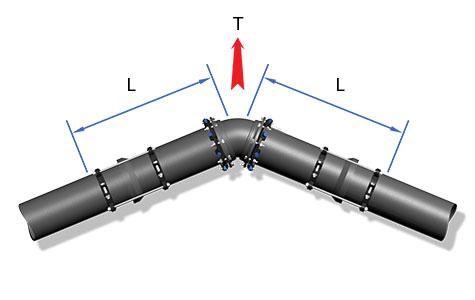
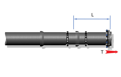
Resultant Thrust: T = 2 • P • A • Sin(θ/2)
Restraint Length: L = | Sf • P • A • Tan(θ/2) |
Fs + ½Rs |
Horizontal bends require restraint of all joints within the calculated length (L) on both sides of the fitting. In many cases, careful planning during installation can reduce the number of joints within the restrained length.
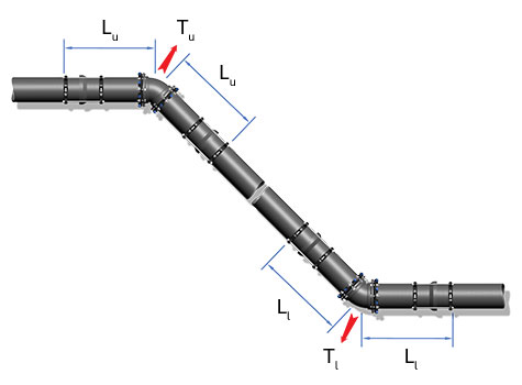
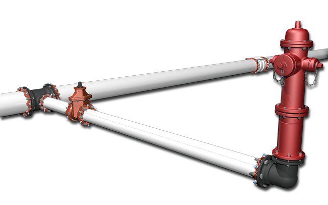
Vertical offsets require restraint of all joints within the calculated lengths (L) on both sides of the upper and lower fittings. When restrained lengths overlap on the diagonal pipe, all joints between the fittings should be restrained.
Resultant Thrust: T = 2 • P • A • Sin(θ/2) | Restraint Length: L = | Sf • P • A • Tan(θ/2) | |
Fs |
Resultant Thrust: T = 2 • P • A • Sin(θ/2) | Restraint Length: L = | Sf • P • A • Tan(θ/2) | |
Fs + ½Rs |
Horizontal bends require restraint of all joints within the calculated length (L) on both sides of the fitting. In many cases, careful planning during installation can reduce the number of joints within the restrained length.
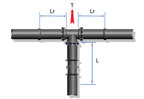
Tee fittings require the restraint of all joints within a calculated length along the branch pipe. The restraint design also requires the selection of a length of pipe along the run (Lr) to be free of joints. See the dialog box labeled 'Select Lr' (visible when Tee fitting type is selected) in the calculation screen for further discussion on this matter.
Resultant Thrust: T = P • Ab
Restraint Length: L = | Sf • (T - Rs • Lr) |
Fsb |
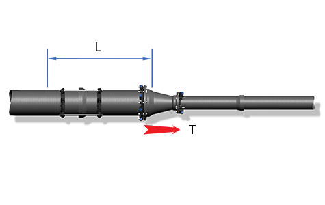
Reducers require restraint of all joints within the calculated length (L) extending from the fitting on the side of the larger pipe.
Resultant Thrust: T = P • (A(large side) - A(small side))
Restraint Length: L = | Sf • P • A • Tan(θ/2) |
Fs + ½Rs |
Dead ends require restraint of all joints within the calculated length (L) extending from the cap. In some installations this length can become fairly large. If this is the case, call EBAA engineering to discuss the use of a thrust collar as an economical alternative.
Resultant Thrust: T = P • A
Restraint Length: L = | Sf • T |
Fsb |
Fire hydrants are typically installed by restraining all of the joints from the main to the mechanical joint shoe at the hydrant.
The hydrant manufacturer should be contacted for recommendations concerning support under the base. Backfill using a good draining granular material.
When all of the joints are restrained, Force B balances Force A.
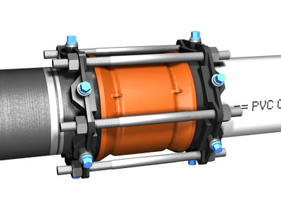
Mechanical joint sleeves and fabricated repair couplings require restraint when they are within the calculated restrained length of other fittings. Standardized M.J. sleeves are easily restrained with common EBAA products while fabricated couplings are somewhat more cumbersome. Call EBAA engineering for assistance in their restraint.
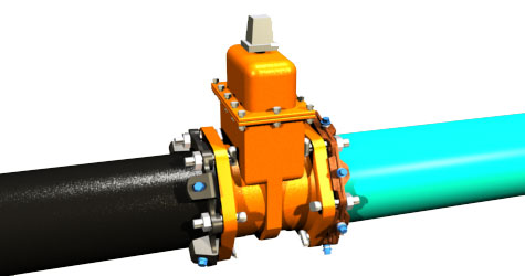
The restraint of valves requires careful consideration in a redundant distribution network. In this case the shutting of the valve can result in pressure forces acting in a direction dependent on the position of the other valves in the system. If this potential exists, it may be necessary to restrain both sides of the valve.
Dead ends require restraint of all joints within the calculated length (L) extending from the cap. In some installations this length can become fairly large. If this is the case, call EBAA engineering to discuss the use of a thrust collar as an economical alternative.
To prevent the intrusion of the cement into the pocket of the restraint rings, a cover of 16 mil polyethylene is required.
Multiply |
by |
To Get |
Acre-Feet | 43,650 | Cubic Feet |
Acre-Feet | 1233.48 | Cubic Meters |
Atmospheres | 14.70 | lbs./sq. in |
Bars | 0.98692 | Atmospheres |
Bars | 1.01972 | Kg/sq. cm |
Bars | 14.5038 | psi |
Centimeters | 0.3937 | Inches |
Cubic Feet | 0.02832 | Cubic Meters |
Cubic Feet | 7.48052 | Gallons |
Cubic Feet | 62.43 | lbs. of Water |
Cubic Meters | 1.30795 | Cubic Yards |
Feet | 0.304801 | Meters |
Foot Pounds | 1.35582 | Newton Meter |
Gallons | 3.7854 | Liters |
Gallons | 0.1337 | Cubic Feet |
Gallon water | 8.3453 | Pounds water |
Multiply |
by |
To Get |
Gallons/min | 8.0208 | Cu. ft./hr |
Inches | 25.40 | Millimeters |
Jiggers | 1.5 | Shots |
Kilometers | 2.20462 | Pounds |
Kilometers | 0.62137 | Miles |
Knots | 1.1508 | Miles/Hour |
Liters | 0.03531 | Cubic Feet |
Liters | 0.26417 | Gallons |
Liters | 61.0237 | Cubic Inches |
Meters | 3.28084 | Feet |
Pounds | 0.4536 | Kilograms |
Pounds Water | 0.01602 | Cubic Feet |
Pounds Water | 0.1198 | Gallons |
Pounds/sq.in. | 0.06895 | Bars |
Pounds/sq.in. | 0.07031 | Kg/sq. cm |
Soil Group | ƒc | c | ƒΦ | φ | γ | Kn | ||||
Trench Type | ||||||||||
DIP | PVC | (psf) | DIP | PVC | (deg) | (pcf) | 3 | 4 | 5 | |
GW, SW | 0 | 0 | 0 | 1.0 | 0.7 | 36 | 110 | 0.60 | 0.85 | 1.00 |
GP, SP | 0 | 0 | 0 | 1.0 | 0.7 | 31 | 110 | 0.60 | 0.85 | 1.00 |
GM, SM | 0 | 0 | 0 | 1.0 | 0.7 | 30 | 110 | 0.60 | 0.85 | 1.00 |
GC, Sc | 0.4 | 0.2 | 225 | 1.0 | 0.6 | 25 | 100 | 0.60 | 0.85 | 1.00 |
CL | 0.5 | 0.3 | 250 | 1.0 | 0.5 | 20 | 100 | 0.60 | 0.85 | 1.00 |
ML | 0 | 0 | 0 | 1.0 | 0.6 | 29 | 100 | 0.60 | 0.85 | 1.00 |
Below is a list of the variables used in the equations for calculating restrained lengths. The equations are shown in the various diagrams under the Restraint Diagrams pull down menu.
A |
Cross sectional area of the pipe [sq. in.] |
Ab |
Cross sectional area of the branch of a tee [sq. in.] |
Al |
Cross sectional area of the large side of a reducer [sq. in.] |
(Ap)b |
Area based on half of the pipe circumference in contact with the soil [sq. ft. / ft.] |
c |
Cohesion of the soil [lbs. / sq. ft.] |
γ |
Soil density [lbs. / cu. ft.] |
D |
Outside diameter of the pipe [ft.] |
fc |
Cohesion modifier coefficient |
Fs |
Frictional resistance acting on half the pipe diameter [lbs. / ft.] |
Fsb |
Frictional resistance acting on the full pipe diameter [lbs. / ft.] |
(Fsb)l |
Fsb on the large side of a reducer [lbs. / ft.] |
fφ |
Friction angle modifier coefficient |
Hc |
Mean depth from surface to pipe centerline [ft.] |
Kn |
Trench compaction modifier |
Kp |
Rankine passive pressure coefficient |
L |
Calculated minimum restrained length [ft.] |
P |
Internal pressure [psi.] |
σ |
Horizontal passive soil pressure [lbs. / sq. ft.] |
Rs |
Bearing resistance acting on the pipe [lbs. / ft.] |
SF |
Safety Factor |
T |
Resultant thrust force [lbs.] |
θ |
Bend angle [degrees] |
We |
Normal force due to the vertical prism load of the soil [lbs. / ft.] |
Wp |
Normal force due to the weight of the pipe [lbs. / ft.] |
Ww |
Normal force due to the weight of the water in the pipe [lbs. / ft] |
W |
We + Wp + Ww = Total Normal force [lbs. / ft.] |
Φ |
Internal friction angle of the soil [degrees] |
Potyondy, J.G.; "Skin Friction Between Various Soils and Construction Materials", Geotechnique, London, England, Volume II, No. 4, December 1961, PP 339-353.
Kennedy, Harold Jr., Shumard, Dennis D., and Meeks, Cary M.; "Investigation of Pipe-To-Soil Friction and Its Affect on Thrust Restraint For PVC and Ductile Iron Pipe", Presented at AWWA Distribution Systems Symposium, September 1989.
Carlesen, Rodger J.; "Thrust Restraint for Underground Piping Systems", Ductile Iron Pipe News, CIPRA, Spring 1975.
DIPRA; "Thrust Restraint Design for Ductile Iron Pipe", Second Edition, 1986.
Lambe, T. William, and Whitman, Robert V.; "Soil Mechanics, Series in Soil Engineering", Massachusetts Institute of Technology, John Wiley and Sons, New York, 1969.
ASTM D 2487; "Classification of Soils for Engineering Purposes."
Uni-Bell Plastic Pipe Association; "Handbook of PVC Pipe, Design and Construction", Dallas, Texas.
EBAA; "Connections, Technical Data for the Water and Wastewater Professional", Bulletins PD-1 through PD-6.
Copyright © 2013 EBAA Iron, Inc. All rights reserved.
The simplest and safest way to design around a live tap is to treat the run of the tapped connection as if it is a dead end. Doing so eliminates any thrust force that would normally develop at the branch. With a live tap there can be a number of factors that come into play. It can be difficult or prohibitive to excavate enough pipe length to determine where the pipe joints are located in order to establish your Lr for the tee calculation. Also, especially with size on size taps, you want to be careful about placing any thrust load on the tapped pipe because of the material that has been cut away from that pipe.
You can determine the restraint length requirement for a dead end and apply it to the piping on each side of the vault. This technique can be used any time you want to prevent a thrust force from being applied.
As the dead end attempts to move in the soil it is resisted by frictional forces around the full pipe circumference for the length of restrained piping. This is how the design equation for the dead end is set up. In actuality there is a small amount of bearing resistance that exists at the end cap and at each of the pipe bells inside of the restrained length. However, the total area of engagement for these is very small and is ignored for the sake of simplicity of design. In the process ignoring the bearing area provides some additional conservatism to the design.
No. For this scenario it is conservative to use the vertical offset calculations. This will provide a longer length when the offset is rotated slightly. However, if the offset is only rotated a few degrees from horizontal you can use the horizontal bend calculations. Doing so is a matter of personal design choice and philosophy.
Yes. In-line valves are there in order to be closed at some time. When a valve is closed it becomes a termination. It is important that the valve is designed as a dead end so that when it is closed 1) the joints of the non-pressurized side of the valve are not compressed and, as a result, over-inserted and that 2) the joints within the required restraint length on the pressurized side do not pull apart. A design option that can be considered, since dead end restraint lengths can be quite long, is to calculate the required restraint length based on the operating pressure if the valves are not closed during the proof testing process.
This is an issue of encroaching restrained lengths and there is no industry consensus on how to deal with them. It becomes a matter of preference by the design engineer. It is important to remember that in these situations when restraint lengths overlap the end result should be that all joints between the fittings in question are restrained. As a result there is no thrust that develops in the pipeline between two fittings. In a situation with multiple fittings with overlapping restraint lengths you should consider where the first unrestrained joint could be potentially and evaluate how thrust at that joint can affect the rest of the piping. As a worst case scenario you can require this length to be restrained as if it were a dead end. Doing this prevents any thrust from being transferred to the fittings in question.
This brings you into a situation involving encroaching restraint lengths. With this situation it is prudent to examine the situation as a 90-degree bend with an eye toward the eventual expansion of the system that includes removal of the dead end and extension of that piping.
The pipe on the oblique leg of the output between the upper bend and the lower bend would likely be fully restrained and, as a result, there would be no thrust force in that portion that could be transferred to the lower bend. The thrust that must be addressed is from the upper horizontal piping.
No. Lr is limited to one pipe length. With this configuration the tee moves ever so slightly into the soil when pressurized. The calculation assumes that there is a slight amount of deflection at the run joints of the tee to develop the triangular shaped bearing resistance along Lr and that the deflection does not transfer to the next pipe joint in order to engage the second piece of pipe.
It doesn’t. This is another situation involving encroaching restrained lengths. The fitting combination needs to be evaluated for situations with the tee in the open and closed conditions. The most conservative result should be applied so that both conditions are covered.
In the restraint design equation for a tee the branch is treated as a dead end. Therefore, a valve at the branch of the tee does not affect how to proceed with the calculation. It doesn’t matter if there is a valve or not and it doesn’t matter if the valve is open or closed.
No, it doesn’t. PVC and ductile iron pipelines typically utilize fittings as defined in AWWA C110, AWWA C153, AWWA C907, and the like. Bend angles from those standards are standardized. It is possible to utilize the program equations found in Connections Bulletin PD-6 "Thrusts Restraint Design Equations and Tables for Ductile Iron and PVC Pipe" and perform manual calculations with the alternative bend angles.
There are over twenty-five Connections Bulletins that cover a variety of joint restraint and EBAA product subjects available on the EBAA Iron website. They can be found at http://www.ebaa.com/documents/connections Six of these deal specifically with the Restraint Length Calculator. They are-
Additionally, you can always contact your regional Product Support Manager or call EBAA Engineering at 1-800-633-9190 for more information.
The "Project Name" and "Site Name" fields on the calculator input screen are simple text fields that you can use to input that information. This information will be displayed on the calculation output on the results screen and in the printed results.
Water hammer is a factor that needs to be taken into account when specifying and designing the various components of a water system. The design of the restraint length requirements does not need to accommodate water hammer for two reasons. 1) The restraint length requirements are designed based on the system test pressure which should be the highest pressure the system ever sees. During this pressure test the internal pressure is static and water hammer is not a factor. 2) Water hammer involves pressure increases for a very short duration of time. As a result, the duration of the pressure increase is too short to have much of an effect on the restraint design of the pipeline.
This is a design preference of the designer and/or system owner. There are municipalities that require specific restraint length calculations for each fitting within a system and others allow for a table of restraint lengths to be utilized throughout a project. A restraint length table is an option that can be applied to systems where conditions are relatively consistent from beginning to end.
No, but the program can be accessed from any device that can access the internet.
Not at this time. All of the values used in the calculations are visible in the program and are shown in Connections Bulletin PD-6 "Thrust Restraint Design Equations and Tables for Ductile Iron and PVC Pipe". These values can be compared to a relevant soils report for comparison and selection of the most appropriate soil condition.
No. Because of the proliferation of operating systems it is currently only available via the internet.
Both programs utilize the design equations that were developed by Rodger Carlson and presented in an article in the Ductile Iron Pipe News (Spring, 1975) entitled "Thrust Restraint for Underground Piping Systems". The primary difference comes in the soil values that are used in those equations. Since 1975, DIPRA has incorporated some slight changes to some of the design equations and has also added some fitting configurations.
The soil friction values in the DIPRA program were based on values developed by J.G. Potyondy and presented in his paper "Skin Friction Between Various Soils and Construction Materials" in Geotechnique (December, 1961). Potyondy developed friction values for a variety of materials used in pilings. The friction values for polyethylene encased pipe were assumed to be a uniform reduction factor applied to the soil friction based on some field observations and, the clay soils within the DIPRA method are assumed to be saturated. The EBAA design program assumes clay soil installations to be non-saturated. Finally, the DIPRA program does not have any calculation values specific to PVC pipe.
The soil values in the EBAA program utilize frictional values that were derived from soil box studies performed on surfaces of ductile iron pipe, ductile iron pipe wrapped with polyethylene, and PVC pipe and several different soils. These studies were performed at EBAA Iron in 1988 and 1989. The results of this testing were published in the proceedings of the 1989 Distribution System Symposium in Dallas, TX with the title "Investigation of Pipe-to-Soil Friction and Its Effect on Thrust Restraint Design for PVC and Ductile Iron Pipe". Also the soil descriptions and values for the EBAA program were kept in line with Unified Soil Classification System, ASTM D2487 "Classification of Soils for Engineering Purposes".
Yes. The resultant thrust forces are the same.
Yes. With each calculation that you wish to include in your saved work, select the "+" button at top of the calculator dialogue box and that will add the current calculation to the saved database.
Doing this will place the calculation in the project database. Once you have finished you calculations the contents of the database can be extracted through the "Spreadsheet" option at the top of the calculator.
The savings vary widely from location to location and situation to situation so it is difficult to quantify in a general way. The variations in pressure, size, soil conditions and labor and material costs all come into play. There have been some non-published studies that suggest that, when all factors are considered, a properly restrained pipeline can cost about half of the same pipeline with thrust blocks.
Doing so increases the overall costs and there is no real way to assign a portion of the resultant thrust force to the thrust block and the rest to the restrained piping.
The intent is to restrain every joint within 16 ft of the fitting. Additional restraint is not needed to meet the restraint length requirements.
The portion of the piping that must be exposed should be fully restrained. Additionally, the remaining piping in the soil should be evaluated and treated as dead ends to avoid transferring thrust forces from the buried portion of the pipeline to the non-buried portion. This is also true any time a portion of a pressurized pipeline must be exposed and potential modifications could alter how the piping reacts to thrust loads.
As with water hammer, the restraint length requirements are based on the system test pressure. When the system is tested the water is not moving, therefore, velocity is not a factor. Also, when the water is flowing, it is doing so at an operating pressure that is much less than the test pressure and, at typical system velocities (2 ft/min or less), the momentum thrust force is a small fraction of the hydrostatic thrust force.
There are a couple of different ways to work with this. The first is to run sample calculations for each scenario and determine which one will result in the longest restrained lengths and apply that soil type to all of those in the project. The second is to make separate calculations for the different areas with the different soil types.
In this case the presence of the polyethylene wrap can be ignored. The polyethylene wrap affects the friction that acts along the barrel of the pipe and is not a consideration when only applied at the fitting.
This is primarily an issue with clay soils and the “phi=0” principle. A discussion of this principle can found in Connections Bulletin PD-5 “Bearing and Frictional Resistance – The Building Blocks of a Restrained System”.
Both should be a consideration. The bearing resistance is based upon the properties of the native soil and the friction resistance is based on the backfill material. There are options within the program for pipe installations where the native soil is a clay and the backfill material is granular.
Not at this time. All of the values used in the calculations are visible in the program and are shown in Connections Bulletin PD-6 “Thrust Restraint Design Equations and Tables for Ductile Iron and PVC Pipe”. These values can be compared to a relevant soils report for comparison and selection of the most appropriate soil condition.
Do these clients permit utilization of soil bearing strength in the design calculations for thrust blocks? Since most likely they do, they should give serious consideration to permitting bearing strength with the design of restraint lengths. The answer to the question is no. Bearing resistance comes into play for tees, horizontal bends, and the vertical up bend of a horizontal offset. To get around this you can calculate the required restraint length for the branch of a tee by treating it as a dead end. You can provide restraint lengths for horizontal and vertical up bends by treating them as vertical down bends at the proper bury depth.
Ductile Iron | Ductile iron pipe meeting ANSI/AWWA C151/A21.51 | |
Poly Wrapped Ductile | Ductile iron pipe in polyethylene encasement meeting the requirements of, and installed per ANSI/AWWA C105/A21.5 | |
PVC | Polyvinyl Chloride (PVC) pressure pipe meeting the requirements of ANSI/AWWA C900, C905, or ASTM D2241 |
Coarse Grained Soils | ||
GW | Well-graded gravels and gravel-sand mixtures, little or no fines | |
SW | Well-graded sands and gravelly sands, little or no fines | |
GP | Poorly graded gravels and gravel-sand mixtures, little or no fines | |
SP | Poorly graded sands and gravelly sands, little or no fines | |
SM | Silty sands, sand silt mixtures | |
GC | Clayey gravels, gravel-sand-clay mixtures | |
SC | Clayey sands, sand-clay mixtures |
Fine Grained Soils | ||
CL | Inorganic clays of low to medium plasticity, gravelly clays, sandy clays, lean clays (backfilled using native soil) | |
ML | Inorganic silts, very fine sands, rock flour, silty or clayey fine sands (backfilled using native soil) | |
CL (granular) |
Cl native soil backfilled with granular material | |
ML (granular) |
ML native soil backfilled with granular material | |
Soils in the groups below require a granular bedding material instead of native soil bedding. Restrained lengths are calculated using GP or SP bedding material. | ||
CH (granular) |
Inorganic clays of high plasticity, backfilled with granular material. | |
MH (granular) |
Inorganic silts, micaceous or diatomaceous fine sands or silts, elastic silts, backfilled with granular material. |
Soil Group | ƒc | c | ƒΦ | φ | γ | Kn | ||||
Trench Type | ||||||||||
DIP | PVC | (psf) | DIP | PVC | (deg) | (pcf) | 3 | 4 | 5 | |
GW, SW | 0 | 0 | 0 | 1.0 | 0.7 | 36 | 110 | 0.60 | 0.85 | 1.00 |
GP, SP | 0 | 0 | 0 | 1.0 | 0.7 | 31 | 110 | 0.60 | 0.85 | 1.00 |
GM, SM | 0 | 0 | 0 | 1.0 | 0.7 | 30 | 110 | 0.60 | 0.85 | 1.00 |
GC, Sc | 0.4 | 0.2 | 225 | 1.0 | 0.6 | 25 | 100 | 0.60 | 0.85 | 1.00 |
CL | 0.5 | 0.3 | 250 | 1.0 | 0.5 | 20 | 100 | 0.60 | 0.85 | 1.00 |
ML | 0 | 0 | 0 | 1.0 | 0.6 | 29 | 100 | 0.60 | 0.85 | 1.00 |
1.5 to 1 is recommended as an explicit factor of safety for calculating restrained lengths in most installations. This factor, combined with the conservative values used in these calculations, generate very conservative restrained lengths. Severe conditions and critical installations may require higher factors.
1.0 to 1
1.5 to 1
2.0 to 1
2.5 to 1
3.0 to 1
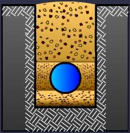
Type 3
Pipe bedded in 4 inches minimum loose soil. Backfill lightly consolidated to top of the pipe.
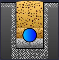
Type 4
Pipe bedded in sand, gravel, or crushed stone to a depth of 1/8 pipe diameter, 4 inch minimum. Backfill compacted to top of pipe. (Approximately 80 percent Standard Proctor, AASHTO T-99)
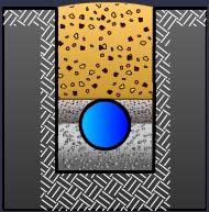
Type 5
Pipe bedded in compacted granular material to the centerline of the pipe, 4 inches minimum under the pipe. Compacted granular or select material to top of pipe. (Approximately 90 percent Standard Proctor, AASHTO T-99)
Depth of bury is measured in feet to the top of the pipe for the calculations within this program. In the case of a vertical offset, please enter the depth of the upper fitting at this time.
Restrained length calculations are based on the highest pressure that the pipeline will be subject to. Since test pressures are typically higher than the operating pressure, they are used in the calculations. Please enter a test pressure between 50 psi. and 350 psi. For test pressures above 350 psi. please contact EBAA for assistance.
This program supports the nominal sizes of 3" through 48", standardized mechanical joint fittings meeting the requirements of ANSI/AWWA C110/A21.10 or ANSI/AWWA C153/A21.53.
Horizontal Bend
Vertical Offset
Vertical Offset with Symmetrical Return
Tee
Reducer
Dead End
This program supports the nominal pipe sizes of 3" through 48" for both Ductile Iron and PVC pipe.
The restrained length calculations performed by this program are applicable to fittings whose restrained lengths do not interfere with the restrained lengths of other fittings. When restrained lengths do overlap, the designer must evaluate the combination as a whole. In some instances, combinations of fittings act to cancel some thrust forces, thus simplifying the necessary calculations.
90°
45°
22 ½ °
11 ¼ °
Like the depth of bury entered in the Data Input Screen, the low side depth of a vertical offset is measured in feet to the top of the lower pipe. This program is able to calculate restrained lengths for pipelines buried up to 32 ft.
This program supports the nominal pipe sizes of 3" through 48" for both Ductile Iron and PVC pipe.
In a restrained joint system, the force at the tee is balanced by the soil in two areas. The first is the area of the pipe that is behind the tee. This is the area in which a thrust block would normally be poured. The restrained length of pipe Lr, along the run of the tee and on each side of the tee, encounters passive bearing resistance from the soil that acts perpendicularly to the tee. The restrained length along the branch of the tee connection, Lb, provides frictional resistance that involves the entire circumference of the branch piping.
The minimum attached length of pipe (Lr) to extend in each direction along the run of the tee is a user specified quantity and this program is used to calculate the restrained length along the branch (Lb). The length of pipe (Lr) must be of solid pipe without joints, fittings, etc. Consideration in specifying this length must be given not only to the job layout, but also to the practicalities of installation.
This program supports the nominal pipe sizes of 3" through 48" for both Ductile Iron and PVC pipe.